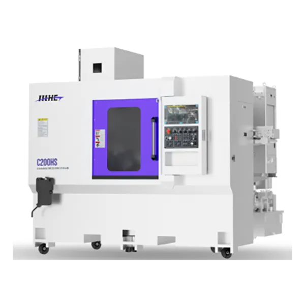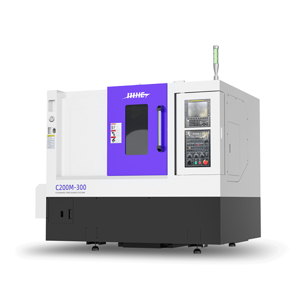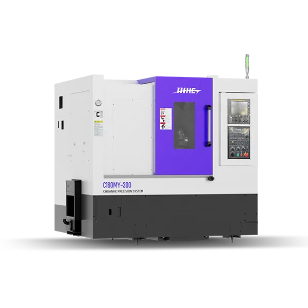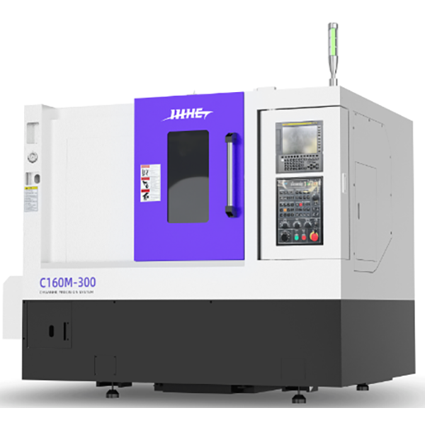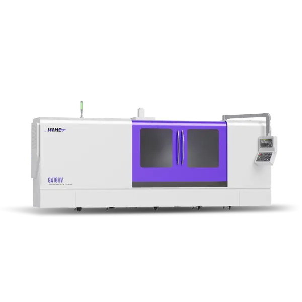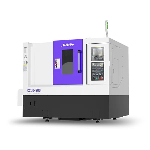
C200-300 Lathe Technical Specification
1.1Structural Design-The machine adopts an integral 30° slant-bed structure, which not only conforms to ergonomic principles but also enhances rigidity through three key engineering measures:
Structural Pre-analysis:During the preliminary design phase, finite element analysis (FEA) is employed to simulate the mechanical behavior of key components such as the bed and guideways, precisely locating stress concentration zones under heavy cutting or high-speed motion conditions.
Deformation Suppression Control:Through optimization of the rib layout and wall thickness distribution, deformation induced by thermal and mechanical loads during machining is effectively minimized and strictly controlled.
Rigidity Assurance Logic:Through force chain analysis, cutting forces are evenly distributed across the entire bed structure, preventing localized stress overload and providing a stable foundation for high-precision machining.
1.2 Material and Process-The main body of the equipment is made of HT300 high-grade resin sand precision castings, naturally offering the following advantages:
Vibration and Noise Reduction:The graphite flakes within the cast iron can absorb cutting vibration energy, reducing chatter marks during machining.
Double Aging Process:Artificial aging rapidly relieves the residual stresses generated during casting cooling, preventing deformation in subsequent machining. Natural aging slowly releases the remaining residual stresses through temperature cycling, ultimately minimizing residual stress and ensuring equipment accuracy.
1.3 Core Configuration-The equipment comes standard with a 8-station servo turret and a precision hydraulic tailstock, enabling “multi-process composite machining” capability:
Machining Coverage Capability:Through the collaboration of the turret and tailstock, full-range machining can be achieved for workpieces from small shafts of φ5 mm to disc parts of φ300 mm. Typical applications include:
Shafts: One-pass forming of the automobile half shaft’s outer diameter, end face, and thread.
Disks: Compound machining of the flange’s inner hole, outer diameter, and grooving.
Complex Parts:Multi-process integrated manufacturing of hydraulic valve blocks.
Configuration List
| Item | CHUANHE HANGZHOU | |
| Key Specifications | ||
| Machine Model |
C 20 0-300 |
|
| Processing Range | Maximum Swing Diameter Over Saddle | Φ400mm |
| Maximum Turning Diameter | Φ320mm | |
| Standard Turning Diameter | Φ200mm | |
| Swing Diameter Over Cross Slide | Φ300mm | |
| Maximum Turning Length | 300mm | |
| Chuck Size | 8″ | |
| Bar Capacity Diameter | Φ52mm | |
| Spindle | Spindle Nose Type | A2-6 |
| Spindle Bearing Model | Front NN3020 + 100BAR, Rear NN3018 | |
| Spindle Through Hole Diameter | Φ66mm | |
| Spindle Drive Method | Belt Drive | |
| Spindle Transmission Ratio | 1:1.9 | |
| Maximum Torque | 63Nm | |
| Maximum Spindle Speed | 6000rpm | |
| X&Z Axes | Maximum Travel of X/Z Axis | 160+20/320mm |
| Rapid Feed Rate of X/Z Axis | 30 m/min | |
| Guideway Type of X/Z Axis | 30mm Linear Guide Way | |
| Ball Screw Diameter/Pitch of X/Z Axis | Φ32mm/Pitch10(X)/Pitch12(Z) | |
| Positioning Accuracy of X/Z Axis | 0.008/1000mm | |
| Repeatable Positioning Accuracy of X/Z Axis | ≤0.005mm | |
| Motor Power | X Axis Motor | 1.8kW(bisc12b/3000) |
| Z Axis Motor | 1.8kW(bisc12/3000) | |
| Spindle Motor | 11/15kW(BII12/10000) | |
| Hydraulic Station | 1.5kW | |
| Water Pump | 0.55kW | |
| Air Conditioner | 0.3kW | |
| Turret | Turret Model | 80~8T |
| Tool Change Time (Adjacent Tool / Opposite Tool) | 0.2sec/0.5sec | |
| Square Tool Holders | 25mm | |
| Round Tool Holders | Φ32mm | |
| Tailstock | Spindle Internal Taper | MT#4 |
| Core Axis Control Method | Programmable Hydraulic System | |
| Tailstock Body Travel | 270mm | |
| Tailstock Body Movement Method | Mechanical | |
| Others | Standard CNC Controller | FANUC |
| Voltage/Power Requirements | 380V/25KVA | |
| Hydraulic Tank Capacity | 45L | |
| Overall Dimensions (L × W × H) | 2200×1600×2100mm | |
| Equipment Weight | 3100KG | |
Get Free Quote of C200-300 Lathe Technical Specification
Get Free Quote for C200-300 CNC Lathe Technical Specification, Turning Machine Parameters and Detailed Machine Configuration
List of Critical Components
| NO. | Item Name | Model/Specification | Brand |
| 1 | CNC System Controller | FANUC-Oi-TF | FANUC |
| 2 | Servo Drive Motor | bisc12b/3000(X),bisc12/3000(Z) | FANUC |
| 3 | Spindle Bearings | Front NN3020 + 100BAR, Rear NN3018(P4 Grade) | NSK |
| 4 | Guideways | HSR30R2UUC1E+520LH-II(X) HSR30LR2UUC0E+800LH-II(Z) | THK |
| 5 | Ball Screw | SDA3210VAZS-5TTG0+620LC3(X) SDA3212VAZS-5TTG0+755LC3(Z) | THK |
| 6 | Fixture | X3-08A6 | SANLIU (DOMESTIC) |
| 7 | Hydraulic Cylinder | XH-852T | SANLIU (DOMESTIC) |
| 8 | Electrical Components | LC1N0910M5N(AC Contactor) | SCHNEIDER |
| 9 | Turret | 80-8T | MYKUN (TAIWAN CHINA) |
| 10 | Ball Screw Bearings | D-2 BSB2562-SU(X) D-3 BSB3062-SU(Z) | FAG |
| 11 | Lubrication Pump | YET-V2P2 220V | ISHAN (TAIWAN CHINA) |
| 12 | Control Cabinet Cooling | EA-300-1225 | WINHEE (DOMESTIC) |
| 13 | Machine Bed | Meehanite Cast Iron One-piece Slant Bed with Electro-Hydraulic Integration | CHUANHE |
| 14 | Hydraulic Components | HK-2F1-A-B(Chuck) | HYKO (DOMESTIC) |
| 15 | Chip Conveyor | Side and Rear Chain-Type Automatic Chip Conveyor | JIBAO |
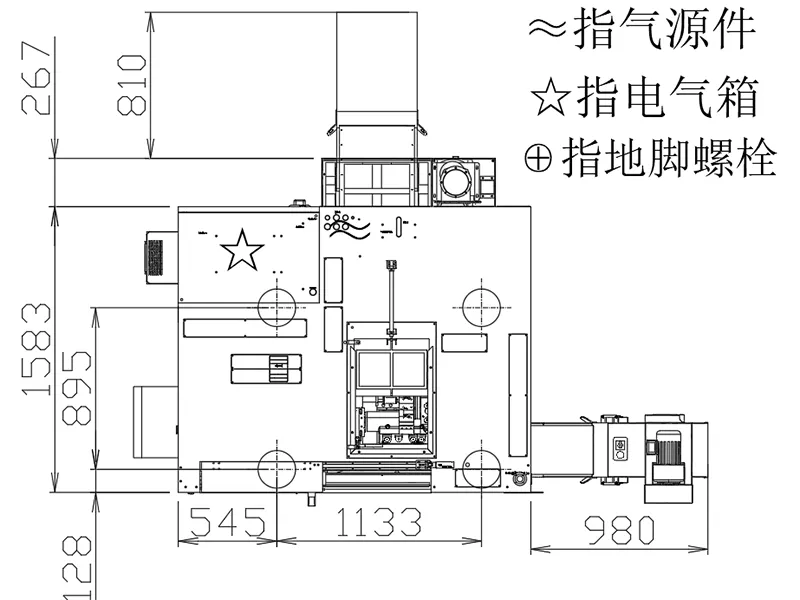
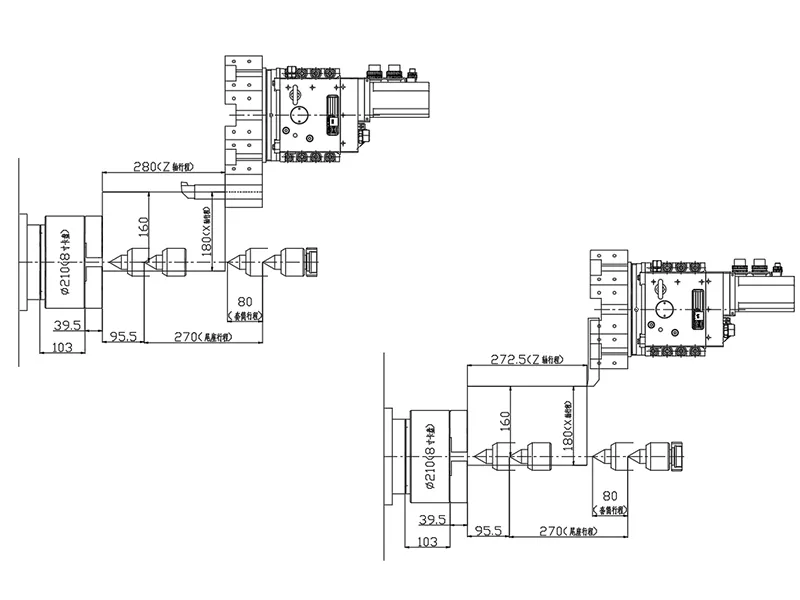
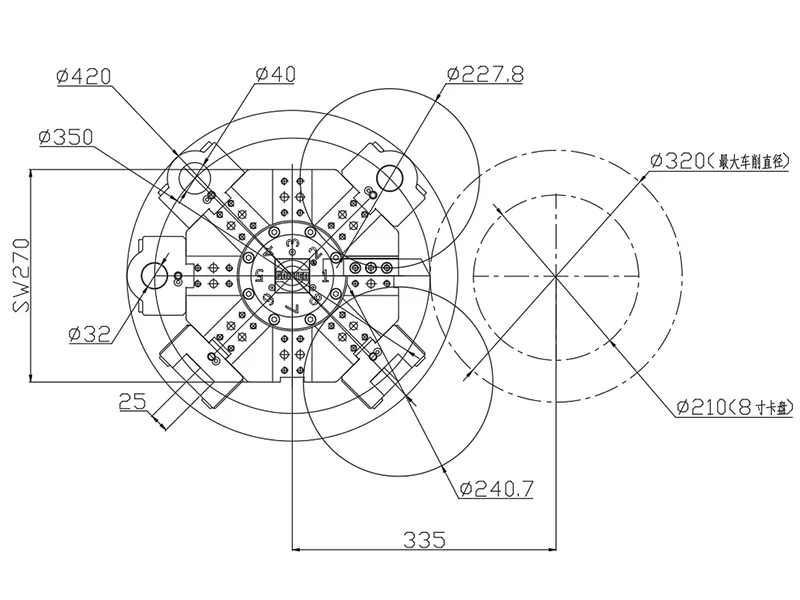
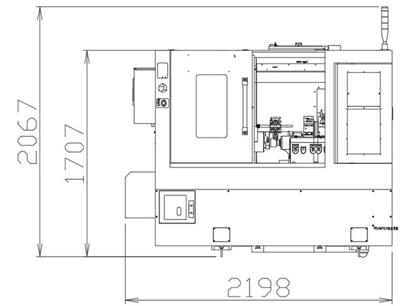
Mechanical Interference Diagram & Overall Dimension Drawing
Optional Item
| NO. | Item |
| 1 | High-Speed Centrifugal Pump |
| 2 | Oil Mist Collector |
| 3 | Safety Door Lock |
| 4 | Bar Feeder |
| 5 | Pneumatic Sliding Door |
| 6 | Tool Setter |
| 7 | Part Catcher |
| 8 | Chip Conveyor |
| 9 | Oil-Water Separator |
| 10 | Linear Encoder |